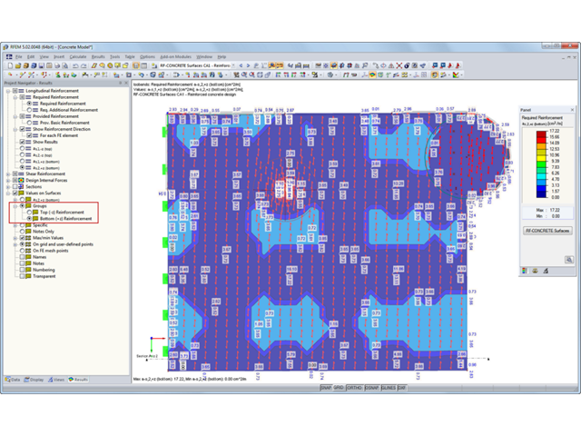
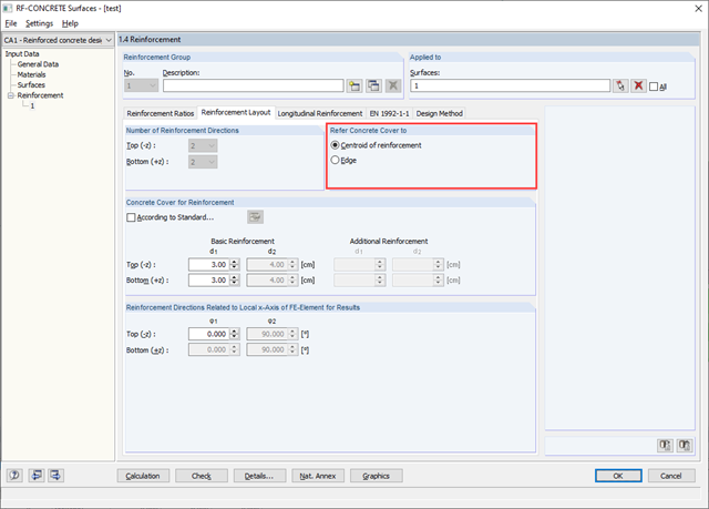
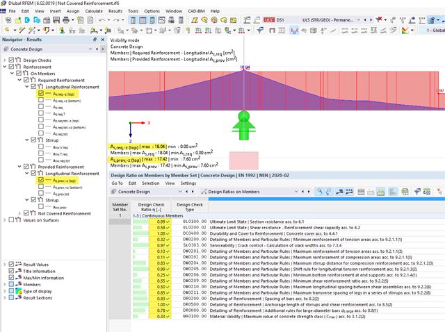
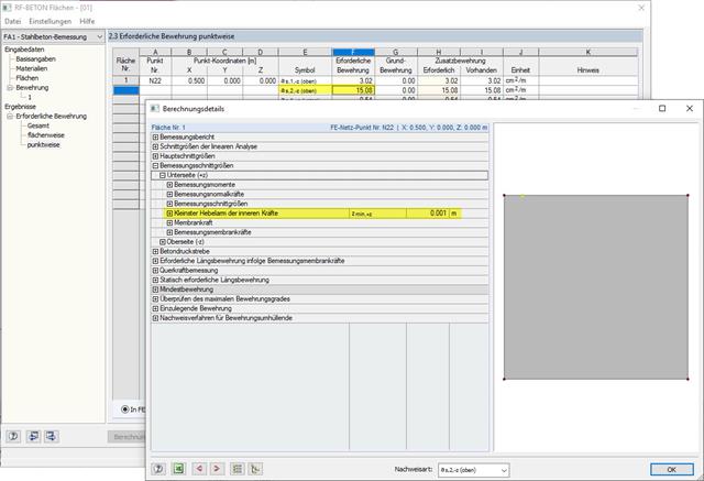
In RF‑CONCRETE Surfaces, I obtain a high amount of reinforcement in relation to a lever arm that is almost zero. How is such a small lever arm of internal forces created?
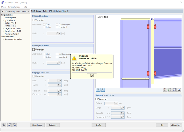
When calculating a connection using the FRAME‑JOINT Pro add-on module, a message appears saying that the value is out of the valid range (existing value: 108, minimum value 100, maximum value 100). What does this message mean?
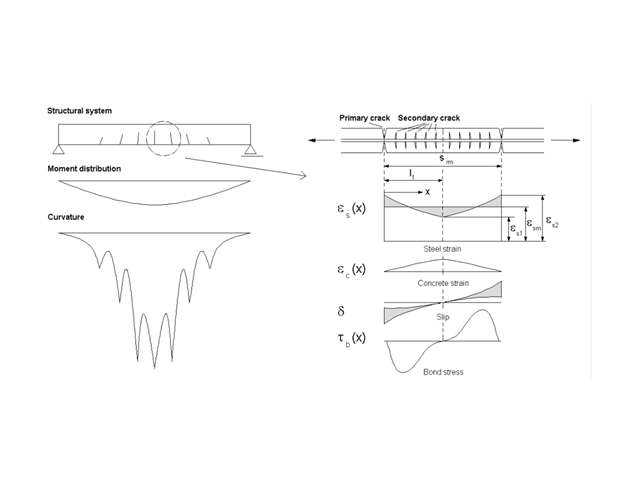
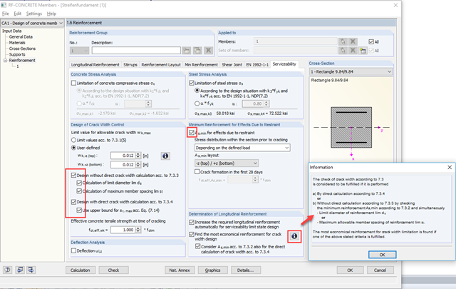
Is the preset crack width of, for example, wk = 0.3 mm also designed for primary cracks? According to the manual, the average strain is considered. Does this ensure that the primary crack does not exceed the value wk = 0.3 mm?
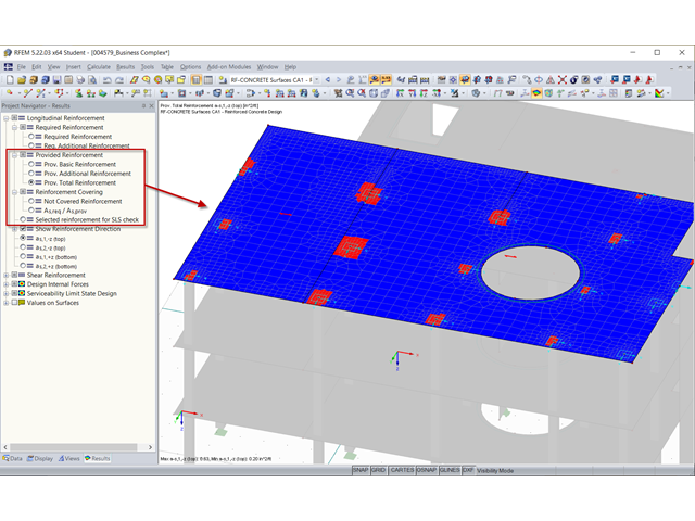
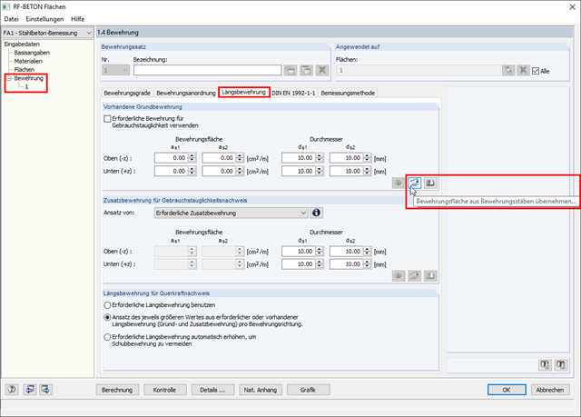
In RF‑CONCRETE Members, I can display the rendering of a provided reinforcement in a structure. Is this also possible for the results from RF‑CONCRETE Surfaces? In the form of single members or meshes?
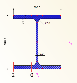
I would like to use the CRANEWAY add-on module to design a suspension crane. Where are design points 0, 1, and 2 for the stress analysis on the bottom flange and for the fatigue design?
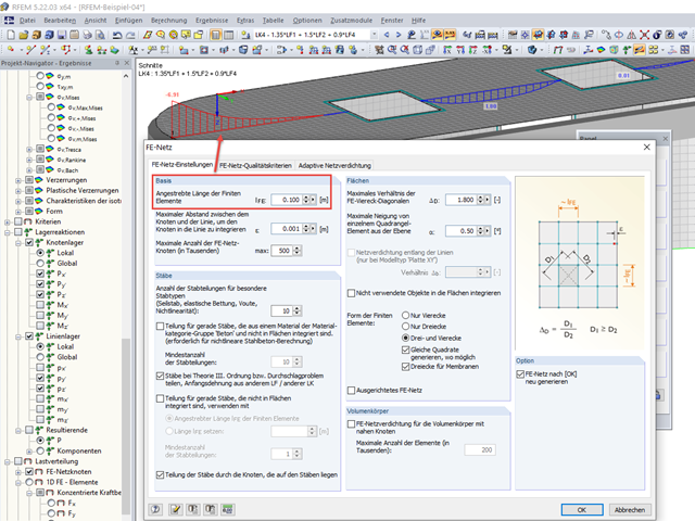
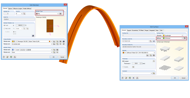
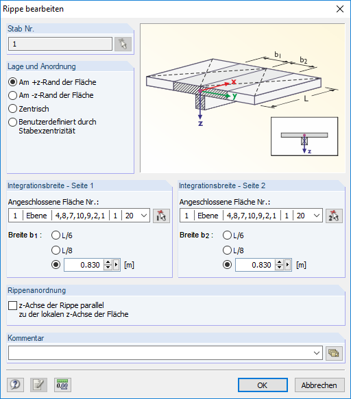
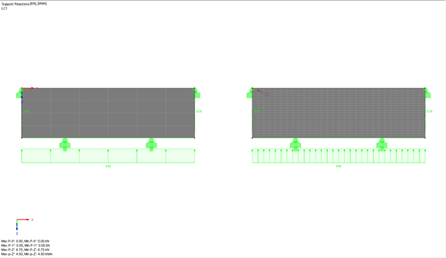
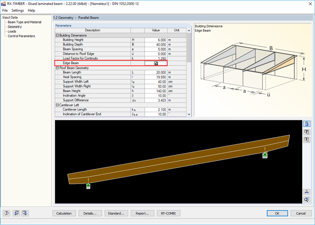
When entering surface loads, it is possible to enter a correction factor to consider the effects of continuity. For the external members or supports of a continuous beam, the factor 0.8 is entered in the model that I have from my colleague. Should the factor for the external section not have to be 0.4?
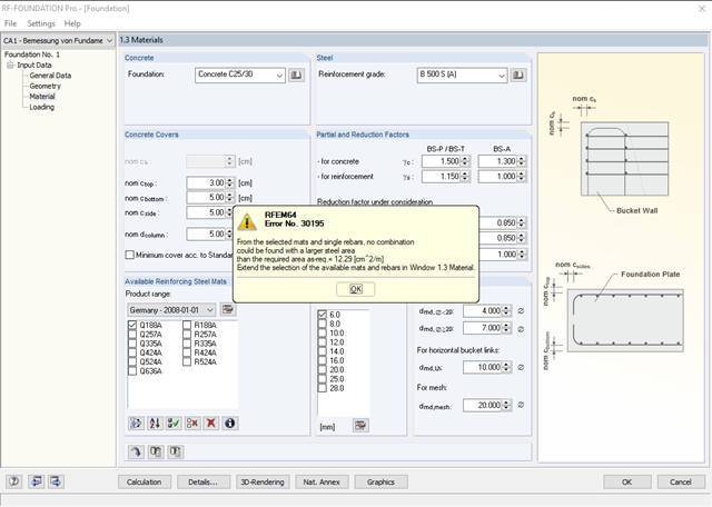
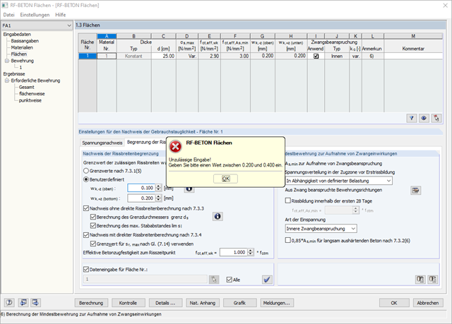
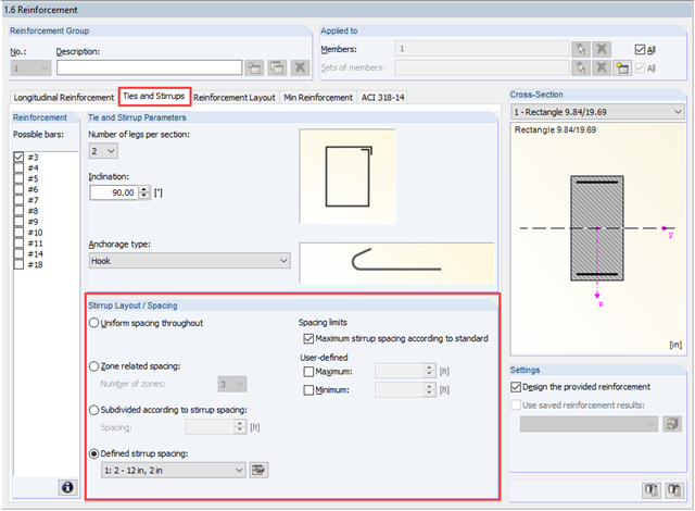
I want to design a crack width of 0.1 mm in RF‑CONCRETE Surfaces. But when entering "0.10 mm" as the limit value, I get an error message saying that only a value between 0.2 to 0.4 mm can be designed.
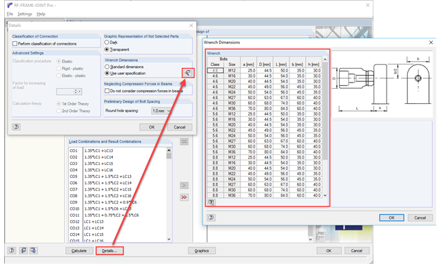
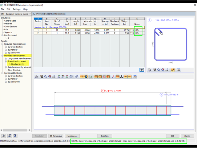
I would like to remodel a connection using FRAME‑JOINT Pro for comparison purposes, but I am having problems with the bolt spacings. Are there any other spacings, or have I overlooked something?
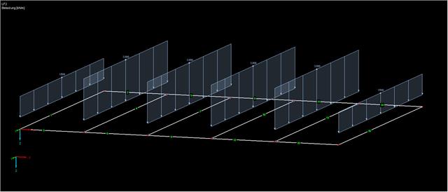
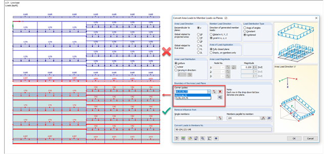
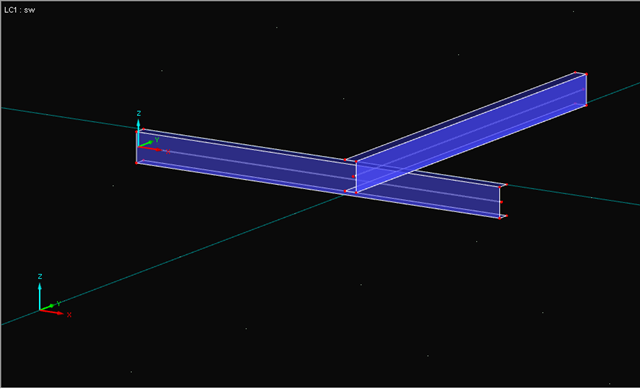
When generating loads with a different arrangement of members within the load plane, I obtain incorrect load values. Why is the load not distributed correctly?
.png?mw=640&hash=80d401daad0df4e59447a570b487668fe3039c9a)